|
Eurocodice 7 |

|

|
|
Eurocodice 7 |
|
|
L'Eurocodice 7 EN 1997 introduce nelle verifiche nei confronti degli stati limiti strutturali e geotecnici gli approcci progettuali che differiscono per le diverse combinazioni di gruppi di coefficienti parziali per le azioni, per la resistenza dei materiali e per la resistenza globale del sistema.
Ogni stato membro della UE rilascia il National Annex (NA) ovvero le specifiche dettagliate per l'applicazione delle direttive contenute nelle EN 1997.
Ad esempio, l'approccio 1 è utilizzato nel Regno Unito e nel Portogallo, l'approccio 2 nella maggior parte dei paesi europei (Germania, Slovacchia, Italia...) per il calcolo della capacità portante e l'approccio 3 nei Paesi Bassi e nella maggior parte dei paesi europei per il calcolo della stabilità dei versanti.
Nelle specifiche vengono riportate i valori dei coefficienti parziali da utilizzare e indicati gli approcci da adottare in fase di progettazione per le diverse opere (capacità portante, ancoraggi, paratie, muri di sostegno....)
Design Approaches
2.4.7.3.4.2 Design Approach 1
| 1. | Except for the design of axially loaded piles and anchors, it shall be verified that a limit state of rupture or excessive deformation will not occur with either of the following combinations of sets of partial factors: |
Combination 1: A1 “+” M1 “+” R1
Combination 2: A2 “+” M2 “+” R1
where “+” implies: “to be combined with”.
NOTE In Combinations 1 and 2, partial factors are applied to actions and to ground strength parameters.
| 2. | For the design of axially loaded piles and anchors, it shall be verified that a limit state of rupture or excessive deformation will not occur with either of the following combinations of sets of partial factors: |
Combination 1: A1 “+” M1 “+” R1
Combination 2: A2 “+” (M1 or M2) “+” R4
NOTE 1 In Combination 1, partial factors are applied to actions and to ground strength parameters. In Combination 2, partial factors are applied to actions, to ground resistances and sometimes to ground strength parameters.
NOTE 2 In Combination 2, set M1 is used for calculating resistances of piles or anchors and set M2 for calculating unfavourable actions on piles owing e.g. to negative skin friction or transverse loading.
| 3. | If it is obvious that one of the two combinations governs the design, calculations for the other combination need not be carried out. However, different combinations may be critical to different aspects of the same design. |
2.4.7.3.4.3 Design Approach 2
| 1. | It shall be verified that a limit state of rupture or excessive deformation will not occur with the following combination of sets of partial factors: |
Combination: A1 “+” M1 “+” R2
NOTE 1 In this approach, partial factors are applied to actions or to the effects of actions and to ground resistances.
NOTE 2 If this approach is used for slope and overall stability analyses the resulting effect of the actions on the failure surface is multiplied by gE and the shear resistance along the failure surface is divided by g R;e.
2.4.7.3.4.4 Design Approach 3
| 1. | It shall be verified that a limit state of rupture or excessive deformation will not occur with the following combination of sets of partial factors: |
Combination: (A1* or A2†) “+” M2 “+” R3
*on structural actions
†on geotechnical actions
NOTE 1 In this approach, partial factors are applied to actions or the effects of actions from the structure and to ground strength parameters.
NOTE 2 For slope and overall stability analyses, actions on the soil (e.g. structural actions, traffic load) are treated as geotechnical actions by using the set of load factors A2.
The table 3.1. below shows which of partial factor are used in each design approch, depending on the type of structure being designed.
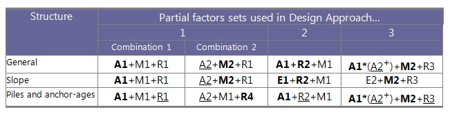
Table 3.1.- Ultimate limit state, design approach (*on structural actions,+ on geotechnical actions)
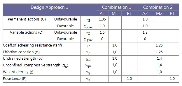
Table 3.2.- Shows the relative magnitude of the key parameters when using Combination 1